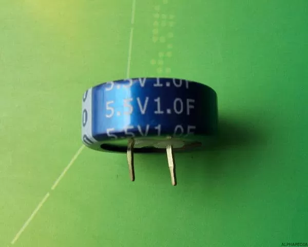
Definition and Meaning of Capacitors
It is an equipment that reduces gases to their liquid or solid form, that is to say, it is the device used to condense fluids from gas to liquid. The main parts of the condenser are compressor, fan, cooling fins and tubes.
A condenser contains the section of the heat exchanger where the refrigerant vapour is compressed and expelled, through the heat exchange coil. After the vapour is compressed, it condenses into liquid to remove the heat through the fan.
Function of Laboratory Condensers
A condenser is an apparatus or element of equipment used to condense (change the physical state of) a substance from its gaseous state to its liquid state.
In the laboratory, condensers are generally used in procedures carried out with organic liquids that enter into a gaseous state by heating with or without a decrease in pressure (application of vacuum), although there are applications in inorganic and other chemical areas.
History and Origin of the Laboratory Condenser
Let’s quickly advance to 18th century Europe, an era known as the Enlightenment, a time and place characterized by the expansion of culture and the acquisition of knowledge. Among the educated and empowered classes of the Enlightenment, science was a fashionable pursuit and lectures on scientific subjects were very popular. Lectures by electricians were among the most popular.
The word electrician originally referred to a person knowledgeable about the nature of static electricity. Electricity was a hot topic in the 18th century and was being explored a lot with electrostatic machines that generated friction charge. While friction is an easy and inexpensive means of separating charge for use in electrical experiments, the amounts of charge available are quite small.
If electricity was to be anything other than an irritating side effect of walking on a carpet, some means had to be found to increase the amount of charge available for the experiments.
The first device to store charge was discovered in the winter of 1745-1746 by two independently working electricians:
Ewald von Kleist (1715-1759), dean of Kammin Cathedral, Prussia (now Kamień, Poland) and Pieter van Musschenbroek ( 1692-1761), professor of mathematics and physics at Leyden University in the Netherlands. The device built by von Kleist consisted of a medicine bottle partially filled with water and sealed with a cork. A nail was pushed through the cork and into the water.
Holding the bottle in one hand, the nail came into contact with the terminal of an electrostatic machine which was allowed to acquire some charge. When von Kleist reached for the nail to be removed from the cork while still holding the bottle, the separate charges were able to come together by flowing through his body. Van Musschenbroek’s device and experiences with it were almost the same as von Kleist’s, but with three major exceptions.
First, a visiting student Andreas Cunæus (1712-1788) made the amazing discovery, not van Musschenbroek himself; second, he made many improvements to the device (most importantly, he removed the water and wrapped the inside and outside of the jar with aluminum foil); soon, scientists across the continent (and Benjamin Franklin in the United States) were building their own new and improved electric charge storage devices.
The refinement of design: filled with water, ink, vinegar, melted butter, wine or beer, and finally nothing (aluminum foil). A glass container was born, partially covered, inside and out, with aluminum foil and the Leyden jar (from Leidsche flesch). Such a device is known today as a condenser.
In 1746, French clergyman and physicist Jean Antoine Nollet demonstrated that electricity could be transmitted instantly over long distances, suggesting that communications could be sent by electricity much faster than a human messenger could transport them. With the connivance of the abbot of the Grand Convent of the Carthusians in Paris, he gathered 200 monks in a long serpentine line with each monk holding the ends of eight-meter long cables to form a chain about a mile long.
Without warning, he connected a Leyden Pitcher to the ends of the line, giving the unsuspecting monks a powerful electric shock and noted with satisfaction that all the monks began to curse and squirm, reacting simultaneously to the shock. A second demonstration was held in Versailles for King Louis XV, this time sending current through a chain of 180 royal guards, as the monks were now uncooperative. The King was impressed and amused as the soldiers jumped simultaneously when the circuit was completed.
What is a Laboratory Capacitor For ?
- Condensers are often used in reflux, where hot solvent vapors from a heated liquid are cooled and allowed to drip.
- This reduces solvent loss by allowing the mixture to heat up for extended periods.
- Condensers are used in distillation to cool the hot vapors, condensing them into liquid for separate collection.
- For fractional distillation, an air condenser or Vigreux is generally used to slow down the rate at which the hot vapours rise, giving better separation between the different components of the distillate.
- For micro scale distillation, there are devices available on the market which include the “pot”, the Claisen head and the condenser fused into one piece. This reduces the retention volume and avoids the need for frosted glass joints preventing contamination by grease and air leakage.
Use of Condensers
- In a laboratory, a condenser is a piece of laboratory glassware used to cool hot vapors or liquids.
- A condenser usually consists of a large glass tube containing a smaller glass tube that runs its entire length, inside which hot fluids pass.
- The ends of the inner glass tube are usually equipped with frosted glass seals that fit easily with other glass items.
- The top end is usually left open to the atmosphere, or ventilated through a bubbler or drying tube to prevent water or oxygen from entering.
- The outer glass tube usually has two hose connections, and a coolant (usually tap water or cold water/anti-freeze mixture) is passed through.
- For maximum efficiency, cold water always enters through the lower fitting and exits through the upper fitting. Several condensers can be connected in series, but a high flow rate must be maintained.
Price in Euros and Dollars for a Laboratory Condenser
- KKmoon 1000pcs 50values * 20pcs 1pF-100nF 50V Assorted Ceramic Capacitor Kit: Price: 8.99
- Farad capacitors with DC 2.7 V 350F Supercondenser Volume 35 x 60 mm electrical components: Price: 10,99
- Bluelover 15-50Uf Condenser Motor Cbb65 450Vac Air Conditioning Start Capacitor-E Compressor: Price: 10,50
- Aluminum electrolytic capacitors for LCD TV LED, 5 units, 450 V, 47 UF, 13 x 42 mm: Price: 2,99
Charging a Capacitor
When a battery is connected to a resistor and a capacitor in series, the initial current is high as the battery transports the charge from one plate of the capacitor to the other. The charging current is asymptotically close to zero when the capacitor is charged to the battery voltage. The charge of the capacitor stores energy in the electric field between the capacitor plates. The charge rate is typically described in terms of an RC time constant.
From the definition of voltage as the energy per unit load, one would expect the energy stored in this ideal capacitor to be only QV. That is, all the work done on the load when moving it from one plate to another would appear as stored energy. But, in fact, the above expression shows that only half of that work appears as stored energy in the capacitor. For a finite resistor, it can be shown that half of the energy supplied by the battery for charging the capacitor is dissipated as heat in the resistor, regardless of the size of the resistor.
Circuits of a Capacitor
Each terminal is connected to a metal plate, but these two plates are separated by an insulator (like air), which means that no load can move between them. In addition, we will add a switch that starts in the “open” position. When the switch is open, nothing happens: the lower metal plate is “grounded” and the upper metal plate is disconnected from any voltage source. (We will assume that it is also in the “ground” position.)
Therefore, there are no electrical forces between the plates. Now, let’s close the switch and see what happens. Initially, when the current just starts flowing in the circuit, the two plates have no voltage difference between them. But the positive charge moves from the positive terminal of the power supply to the upper plate and begins to build up (the lower plate is on the ground, and the positive charge is pulled towards it by the electrical force).
Note that the current cannot flow between these plates because they are separated. As a positive charge accumulates on the upper plate, the positive charge moves away from the lower plate, leaving it with an equivalent negative charge. The charge will build up until the voltage drop between the two plates is equivalent to the supply voltage, V.
Note that the existence of an electrical force between the plates (and therefore a difference in electrical potential) is clearly seen because one plate is positively charged and the other is negatively charged. In essence, these plates are like a power supply that is “charged” or “energized” by the battery (or other source) in the circuit. In other words, these plates can store electrical energy by accumulating charge.
Such a device involving conductive plates, whatever their shape, is called a capacitor. By studying the circuit below we will see what a capacitor can do. If we close the switch S1 to charge the capacitor; Because S2 remains open, there is no voltage drop in the resistance, so it does not participate in the circuit’s operation. The capacitor will be “charged” until it reaches the voltage V.
The time this process takes depends on several factors: if the cables are truly perfect conductors, the process is instantaneous, but if the cable has some resistance, as it does in reality, then this process takes a finite amount of time. Once the capacitor is charged, we open switch S1; the top plate maintains its charge (because it is not connected to ground), so the voltage across C is still V volts.
Now, close switch S2. The positive charge on the top plate of the capacitor now has a path to ground: through the resistor R. Following the principles of circuit analysis, we know that (initially) the voltage drop across the resistor is V. But as the excess charge on the top plate of the capacitor flows to ground, the capacitor loses its stored energy, which means that its voltage decreases. Therefore, according to Ohm’s law, the current also decreases.
This process continues until the charge in the capacitor is exhausted; at this point, the circuit is “dead” which simply means that there is no more voltage or current through R and C. (By the way, the positive charge in this case can best be seen as traveling to the bottom plate of the capacitor, where it “neutralizes” the negative current that was building up when the capacitor was charged.)
At this point, the capacitor must be recharged to repeat the process. If both switches are closed simultaneously in this circuit, then the capacitor is also charged, but once it reaches its maximum capacity, the only current that flows is through the resistor R. This current can be found using Ohm’s law. Therefore, when fully charged in this circuit, the capacitor is effectively the same as an open switch!
Capacitor Types
The types of capacitors are the following:
Air Cooling: Air Condenser
An air condenser is the simplest type of condenser. There is only one tube, and the heat from the fluid is conducted to the glass, which is cooled by the air. It is related to the replica used by alchemists.
The air condenser is generally used for fractional distillation, and can be packed with some material such as glass beads, metal pieces, or Raschig rings to increase the number of effective plates.
Vigreux Condenser
A Vigreux condenser is a modification of the air condenser. It is generally used as a fractionating column for fractional distillations.
Unlike straight-walled columns, a Vigreux column has a series of indentations pointing downwards on the inner wall that serve to drastically increase the surface area without increasing the length of the condenser. Due to their added complexity, Vigreux columns also tend to be considerably more expensive than traditional straight wall designs.
Water Cooled: Liebig condenser
The Liebig condenser is the most basic water-cooled design. The inner tube is straight, so it is cheaper to manufacture. Although it is named after German chemist Justus Baron von Liebig, he cannot be credited with its invention because it was in use for some time before him. However, it is believed that the device was popularized by him.
The real inventors, all of them making the discovery independently, and the year of the invention were the German chemist Christian Ehrenfried Weigel in 1771, the French scientist, P. J. Poisonnier, in 1779 and the Finnish chemist Johan Gadolin in 1791.
Liebig himself incorrectly attributed the design to the German pharmacist Johann G-ttling, who had made improvements on Weigel’s design in 1794. The Liebig condenser is much more efficient than a simple replica due to its use of liquid cooling. Water can absorb much more heat than the same volume of air, and its constant circulation through the water jacket keeps the temperature of the condenser constant. Therefore, a Liebig condenser can condense a much higher flow of incoming steam than an air condenser or a replica.
Graham Condenser
A Graham capacitor has a spiral coil that runs the length of the capacitor. There are two possible configurations for a Graham capacitor. In the first, the spiral contains the refrigerant, and condensation takes place on the outside of the spiral. This configuration maximizes flow capacity as vapors can flow over and around the coil.
In the second configuration, the jacket tube contains the refrigerant, and condensation takes place inside the coil. This configuration maximizes the collected condensate, as all vapors must flow through the entire length of the coil, thus having a prolonged contact with the refrigerant.
Dimroth Capacitor
The Dimroth capacitor is somewhat similar to the Graham capacitor. It has an internal double spiral for the cooling medium so that both the inlet of the refrigerant and the outlet are at the top. Vapors travel through the jacket from the bottom to the top. Dimroth condensers are more efficient than conventional coil condensers. They are often found in rotary evaporators. It is named after Otto Dimroth.
Allihn Capacitor
The Allihn condenser or bulb condenser or simply reflux condenser is named after Felix Richard Allihn. The Allihn condenser consists of a long glass tube with a water jacket. There are a number of large and small constrictions in the inner tube, each increasing the surface area over which the steam components can condense. Ideal for laboratory scale reflux.
Friedrichs Condenser
A Friedrichs condenser (sometimes called a Friedrich condenser), also known as a spiral finger condenser, consists of a large internal spiral cold finger type capillary tube arranged within a large cylindrical housing. Coolant flows through the internal cold finger; consequently, vapors rising through the housing can condense on the cold finger as it cools.
Compared to a Graham condenser of similar size, which also includes a spiral inner tube, the Friedrich condenser often provides a more efficient condenser because the Friedrich condenser provides a larger effective surface area for cooling.
That is, the vapors can be cooled not only by the refrigerant flowing through the internal cold finger, but also by the inner wall of the cylindrical housing. The spiral cold finger device now known as the Friedrichs condenser was invented by Fritz Walter Paul Friedrichs, who published a design for this type of condenser in 1912.
Electrical Capacitors
It is a device for the storage of electric charge. Simple capacitors consist of two plates made of an electrically conductive material (e.g., a metal) and separated by a non-conductive or dielectric material (e.g., glass, kerosene, mica, oil, paper, tantalum, or air).
The Leyden jar is a simple capacitor. If an electrical potential (voltage) is applied to the plates of a capacitor (for example, by connecting one plate to the positive terminal and the other to the negative terminal of a storage battery), the plates will be charged, one positively and one negatively. If the externally applied voltage is then removed, the capacitor plates remain charged, and the presence of the electrical charge induces an electrical potential between the plates.
This phenomenon is called electrostatic induction. The capacity of the device to store electrical charge (i.e., its capacitance) can be increased by increasing the area of the plates, decreasing their separation or changing the dielectric. The dielectric constant of a particular dielectric is a measure of the unit capacity of the dielectric. It describes the ratio of the capacitance of a dielectric-filled capacitor to a capacitor of the same size with a gap between the plates. Capacitors are used in many electrical and electronic devices.
The main capacitor ratings are non-polarized (used for AC circuits) and polarized (used for DC circuits). Capacitors can also be classified as fixed or variable. One type of variable capacitor, previously used in radio and television tuning circuits, consisted of two sets of semi-circular plates, one fixed and the other mounted on a moving shaft. As the axis is rotated, the overlapping area of the two plates increases or decreases, which increases or decreases the capacitance. These devices have been largely replaced by frequency synthesizers and a special type of solid-state diode, known as a varactor, whose capacitance changes with the reverse bias voltage across it.
Condenser in Physics
It is an electrical device characterized by its ability to store an electrical charge
Series Capacitor
- When capacitors are connected in series, the total capacity is less than any of the individual capacities of the series capacitors.
- If two or more capacitors are connected in series, the overall effect is that of a single capacitor (equivalent) having the total sum of the plate clearances of the individual capacitors.
- An increase in plate spacing, with all other factors unchanged, results in a decrease in capacity.
- Therefore, the total capacity is less than any of the individual capacitor capacities.
Parallel Capacitor
When capacitors are connected in parallel, the total capacity is the sum of the capacities of the individual capacitors.
If two or more capacitors are connected in parallel, the overall effect is that of a single equivalent capacitor having the total sum of the plate areas of the individual capacitors.
An increase in plate area, with all other factors unchanged, results in an increase in capacity.
Therefore, the total capacity is greater than any of the capacities of the individual capacitors.
Ceramic Capacitor
A ceramic capacitor uses a ceramic material such as dielectric. Ceramic was one of the first materials used in the production of capacitors, as it was a known insulator. Many geometries were used in ceramic capacitors, of which some, such as tubular ceramic capacitors and barrier layer capacitors are obsolete today due to their size, parasitic effects or electrical characteristics.
The types of ceramic capacitors most frequently used in modern electronics are the multilayer ceramic capacitor, also called multilayer ceramic chip capacitor (MLCC) and the ceramic disc capacitor. MLCCs are the most widely produced capacitors with an amount of approximately 1 billion devices per year. They are manufactured with SMD (surface mount) technology and are widely used due to their small size.
Ceramic capacitors are generally manufactured with very small capacitance values, typically between 1nF and 1µF, although values up to 100µF are possible. Ceramic capacitors are also very small in size and have a low maximum voltage rating. They are not polarized, which means that they can be safely connected to an AC source. Ceramic capacitors have a high frequency response due to the low parasitic effects, such as resistance or inductance.
Flat Capacitors
Flat-plate condensers work by removing heat from the gas or steam; once enough heat is removed, liquefaction occurs. For some applications, all that is necessary is to pass the gas through a long tube (usually arranged in a coil or other compact form) to allow the heat to escape into the surrounding air.
A heat-conducting metal, such as copper, is commonly used to transport steam. The efficiency of a condenser is often improved by attaching fins (i.e., flat sheets of conductive metal) to the tube to accelerate heat removal. Commonly, such condensers employ fans to force air through the fins and remove the heat.
Variable Condensers
Capacitors in which the capacity is varied by mechanical means, e.g. by rotating an axis; Processes of their manufacture that use the variation of the effective area of the electrode due to the rotation of partially cylindrical, conical or spherical electrodes.
Commercial Capacitors
A commercial condenser is larger, as it needs to cool or heat a much larger space. Commercial systems are also different in terms of components such as thermostats, condenser fans, compressors, evaporators, fans and dampers. Usually placed on the ceiling, it is an excellent space-saving solution. It prevents noise pollution in the building.
It is a perfect solution for maintenance, since none of the activities are interrupted during repairs and replacements. A commercial condenser consists of multiple pipes and trays for the purpose of drainage to ensure complete evaporation and eliminate the possibility of overflow.
Mica condenser
Mica is a group of natural minerals. Silver mica capacitors are capacitors that use mica as a dielectric. There are two types of mica capacitors: subject mica capacitors and silver plated mica capacitors. Fixed mica capacitors are now considered obsolete because of their inferior characteristics. Silver mica capacitors are used instead. They are made by interleaving mica sheets coated with metal on both sides. This assembly is encapsulated in epoxy to protect it from the environment.
Mica capacitors are generally used when the design requires stable and reliable capacitors of relatively small values. They are low loss capacitors, which allow them to be used at high frequencies, and their value does not change much over time. Mica minerals are very stable electrically, chemically and mechanically. Due to their specific bonding to the crystal structure, they have a typical layered structure. This allows the manufacture of thin films in the order of 0.025-0.125 mm. The most commonly used are Muscovite and Phlogopite.
The first has better electrical properties, while the second has a higher temperature resistance. Mica is found in India, Central Africa and South America. The high variation in the composition of the raw material leads to a high cost needed for inspection and classification. Mica does not react with most acids, water, oil and solvents.
Plastic Condenser
An impact resistant compact plastic condenser comprising a plastic casing that has two side walls enclosing at least one heat transfer disc arranged between those side walls that divide the casing into at least one cooling cell. And at least one steam cell. Means are provided to retain such a disk in a sealed pillar against such end walls of such sidewalls, each such cell having an inlet port and an outlet port.
Other Laboratory Materials and Instruments in ALPHAPEDIA

THE BEST BEAKER PRICE

CLAY TRIANGLE: Use, Function and Price
LABORATORY BALANCE: Definition, Use and Parts
LAB STANDS DOUBLE TOP WIRE CLAMPS ¿ What it´s for ?

THE CRUCIBLE USES

LABORATORY SHAKER: Use, Types and Price
Other Topics of Interest in ALPHAPEDIA

FREE BACHELOR IN VISUAL ARTS

FREE MASTER DEGREE IN FINE ARTS

FREE FINANCE COURSE

FREE DOCTORATE IN CIVIL ENGINEERING

FREE TRAINING COURSE

FREE CAKE DECORATION COURSE
Image and Drawing of the Condenser
